Description
DESCRIPTION
The D331AT Sync & Gate Module is designed to deliver repetitive bursts of pulses. The bursts can last a set duration of time and can be repeated with a set repetition interval. If the duration time is set too long so that a second repetition command is requested during a burst, it is ignored, the requested burst duration is completed and an error is indicated.
Full external control and monitoring is provided for both the gate (repetition and duration) and pulse (frequency and width) function.
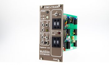
The left-hand side of this module provides the front panel power switch, power-on/fault bi-colour LED, synchronising sockets, single pulse button and indicator for the GATE waveform.
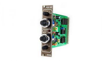
The right-hand side of this module provides control of the gating function so that bursts of pulses can be delivered at accurately set intervals (repetition) for accurately set periods (duration). The pulse frequency and width would be set by a D332T – Pulse.
Features
GATE Repetition
Total Range: 1-1100s
Divider: Internal jumper for total range 0.1-110s
Control: 10 turn (3600 degree) control with lock marked 1-11 turns and sub-marked in 1/10 and 1/50 turn.
Accuracy: ±1% through dial range
Multiplier: x1; x10; x100
GATE Duration
Total Range: 0.1-110s
Divider: Internal jumper for total range 0.01-11s
Control: 10-turn (3600 degree) dial control with lock marked 1-11 turns and sub-marked in 1/10 and 1/50 turn
Accuracy: ±1% through dial range
Multiplier: x0.1; x1; x10
Warning Indicator
Error: Red LED that illuminates if the Repetition requested is set too high for the set Duration
Gate Synchronisation
Ext. Input: TTL input for external control of the Gate signal
Triggers at +1.5V
Maximum input ±15V
Active high
Selector:
‘EXT’ – External control of Gate Repetition and Duration [Left], ‘INT’ – Internal control of Train Repetition and Count [Centre], ‘CONT’ – Pulses continuously enabled [Right]
Indicator: Amber LED, on for Duration of Train
Sync. Output: TTL output for external monitoring of Train waveform
Optionally:- +15V positive pulse by on-board jumper (J3)
PULSE Synchronisation
Ext. Input: TTL input for external control of Gate signal
Triggers at +1.5V
Maximum input ±15V
Active high
Selector:
External control of Pulse Frequency and Width [Left], External control of Pulse Frequency (Int. Width-D332T) [Centre], Internal control of Pulse Frequency and Width (D332T) [Right]
Single: Push button to give a single output pulse irrespective of any other settings
Sync. Output: TTL output for external monitoring of Pulse waveform
Optionally:- +15V positive pulse by on-board jumper (J2)
Synchronisation Sockets
Connectors: Ext. Input and Sync Output sockets are Lemo type.
Mating plugs and leads are available – see Accessories.
GALLERY
DOWNLOADS
Product Information
D330 MultiStim Brochure
D330 MultiStim Operating Modes
D330 MultiStim Module Selection Flowchart
References
Publications which cite use of the Digitimer D330 MultiStim can be found on Google Scholar.
FAQS
Of course, feel free to contact us to discuss your requirements, but perhaps you should take a look at our comprehensive D330 operating mode notes and module selection flowchart (see above) before doing so.
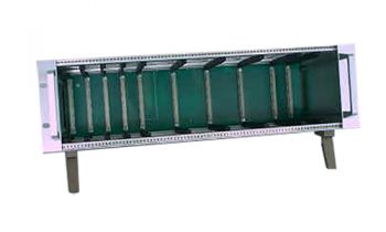
A single D337 rack supports 2 -10 channels of stimulation. In addition, multiple D337 racks can be linked by a “sync” cable allowing this maximum to be increased further. Please remember that for safety reasons any empty bays must have blanking panels fitted to protect the user from possible electric shock.
The output sockets on the MultiStim fit 2mm plugs. We can supply these in packs of 10 with either black or red insulation (part number NL822P/10-Blk or NL822P/10-Red).
This is the simplest possible MultiStim setup. If your software and hardware is capable of producing the required stimulation timing characteristics (i.e pulse frequency and duration), then all you require is a D337 Case, D334B Sync Module, the required number of dual stimulator modules/blanking panels and an appropriate cable (usually Lemo plug to BNC plug) to link the interface to the MultiStim. We also recommend a D335 meter in order to easily monitor the output current.
The D337 Case is specifically designed to hold timing and pulse generator modules in the first (left-hand) four bays. Dual width stimulator modules (D333H or D343) will ONLY operate correctly if they are placed in the remaining 10 bays.
The D333H and D343 modules include an overload LED which serves to warn the user if the current requested or required cannot be supplied by the stimulator. The D333H modules have an upper limit of 1A, so if the impedance of the preparation and the voltage settings are high enough, the module will reach the maximum output current and indicate an overload. The same effect can be seen with the D343 except this is a constant current device and will supply up to 500mA until it reaches a compliance limit of 100V. If you run into the above problems, consider whether you need to have the output settings so high and also check that your preparation and electrodes provide a low impedance connection.


