Description
DESCRIPTION
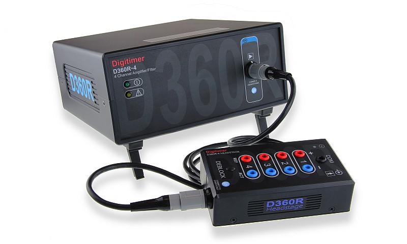
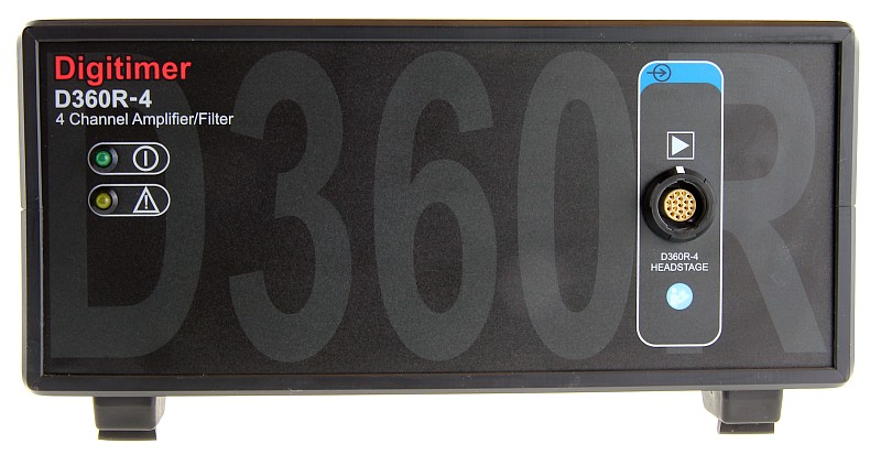
The new D360R Multi-channel Isolated Research Amplifiers are intended for electroencephalography (EEG), electromyography (EMG) or evoked potential (EP) studies in a human research environment. Based on the design of our extremely popular 8-channel D360 Isolated Patient Amplifier, the new D360R-4 is the first of this new family of amplifiers and provides a compact, cost-effective, but highly-specified 4-channel research equivalent. Two channel (D360R-2) and 8-channel (D360R-8) variants of the D360R are being planned for future development.
The four channel D360R-4 has been designed to meet all of the electrical requirements of the medical electrical standard IEC 60601-1, including but not limited to:-
(i) full electrical isolation of the input circuit
(ii) meeting of or exceeding creepage and clearance minimum requirements
(iii) ensuring inputs are single fault condition safe.
Unlike the 8-channel D360, the D360R-4 is NOT a medical device and its use is limited to animal or human research applications.
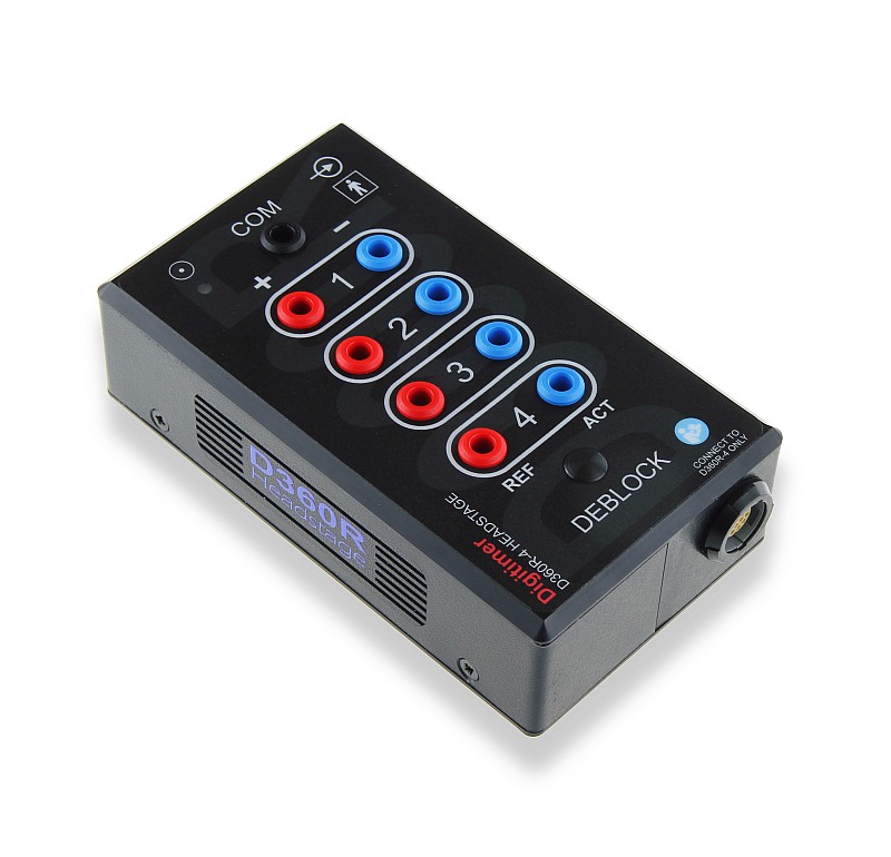
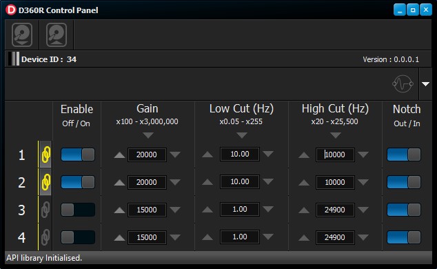
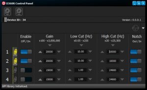
The D360R-4 comprises a main amplifier unit, a remote pre-amplifier headstage with 4 pairs of differential inputs (plus Common) and dedicated Windows-compatible Client Software. The software provides a virtual front panel for the adjustment of settings, including low-pass and high-pass filters as well as amplifier gain. The pre-amplifier headstage is attached to the main amplifier via a fully detachable 2m long cable, which is easily replaced if it becomes damaged during use.
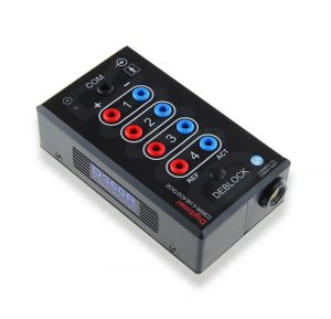
The D360R-4 provides software and hardware de-block capabilities which can be useful to settle the amplifier inputs following electrode placement or re-positioning. In addition, a TTL controlled de-block function allows a precisely timed external de-block to be applied in situations where a large stimulation artifact might obscure a short latency response.
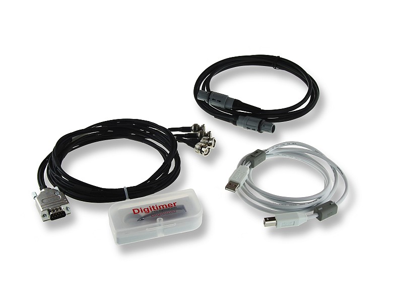
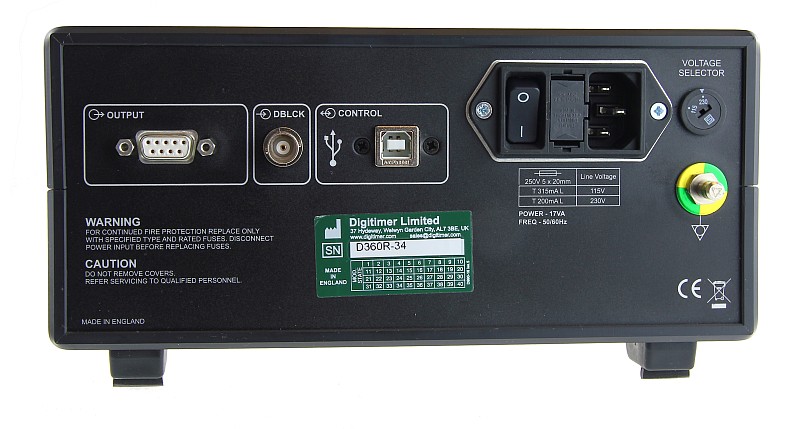
Analogue signal outputs mean that the D360R-4 is fully compatible with a vast array of commercially available data acquisition systems. As a result, the user can opt to employ their favoured data acquisition and analysis software. Signal outputs are available on the rear panel via a 9-way “D” connector. The D360R-4 is supplied with a “D” to multi-BNC cable for connection to BNC-based data acquisition systems.
The D360R-4 supports system expansion as multiple D360R-4 amplifiers can be connected to a single computer (via several USB sockets or hub) to allow multiples of 4 channels to be controlled through a single software interface.
SPECIFICATIONS
Headstage
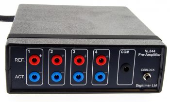
The headstage is a small remote pre-amplifier to which the operator connects the electrodes from the subject to the amplifier. The head stage is small enough to be attached to a subject to permit partial mobility should this be required. The headstage is connected to the main amplifier using a 2m multi-way cable. Digitimer can also supply a 5m long headstage cable (D990-53) where a greater distance is required between the main amplifier and headstage.
- 100MΩ Input impedance
- Independent channel enable/disable (Inputs are connected to COM when a channel is disabled)
- Single COM reference input (1.5mm touch-proof DIN42802 socket).
- Differential Channel Inputs (+ve [ref] –ve[act]), (Red & Blue 1.5mm DIN42802 touch-proof sockets)
Analogue Channels
- Maximum Channels : 4
- CMRR : ≥90dB
The following channel parameters can be independently controlled and are accurate to within ±5%:
- Gain : x100–x3,000,000 (10mV/V–0.33µV/V) 80 gains from x100 to x3,000,000
- Low Cut Filter: 0.05–255Hz, 05–2.5Hz (0.01Hz Steps), 5–62.0Hz (0.25Hz Steps), 62–255Hz ( 1.0Hz Steps)
- High Cut Filter: 20–25,500Hz, 20–1300Hz (5Hz Steps), 1300–25,500Hz (100Hz Steps)
- Notch Filter (50/60Hz) auto-detected based on mains frequency
Outputs
Analogue channel outputs are via a 9-way connector on the rear panel. An output lead is supplied, which breaks-out individual channels to 1m BNC terminated cable for connection to chosen acquisition interface.
Deblock
The deblock provides a means to remove excessive DC from the low pass series capacitors which in certain situations could block the signal. The de-block can be applied in using the Client Software/API, a button press on the headstage or using a precise TTL sync voltage connected to an input BNC on the rear panel. Deblock is applied to all channels.
- Deblock button on headstage, applied whilst button depressed.
- Deblock can be applied using the Client Software or API.
- TTL BNC Input (2 modes)
- Timed – 0.1ms – 10ms (0.1 steps) – triggered on rising edge of TTL BNC input
- Gated– Deblock active for the time TTL BNC input is held high.
Software
Supplied D360R-4 Client Software compatible with Windows10 (32/64bit) and above.
Physical Size
Headstage: 134 x 76 x 39mm, weight: 0.255kg; Amplifier: 228 x 242 x 111mm, weight: 3kg
Safety
The D360R-4 is NOT a medical device and is intended for research use, however, it has been designed to meet all of the electrical requirements of IEC 60601-1, ensuring safety in human research. This includes but is not limited to:
- Input circuit is fully electrically isolated.
- Creepage and clearance meets or exceeds the minimum requirements.
- All inputs are single fault condition safe.
Power Requirements
Mains requirements: 120/240AVC (Switch selected) 50/60 Hz
GALLERY
FAQS
The D360 is certified to the European Medical Device Directive and is suitable for patient use, while the D360R-4 is designed for safe use in human research, but is not a medical device. The D360 incorporates electrode impedance checking via the control software and headstage LEDs; the D360R-4 does not have any electrode impedance checking mode. The D360 allows for internal linking of +ve or -ve electrode inputs, so multiple channels can share a single reference electrode. The D360R-4 operates in standard differential mode with an additional Common input. The D360 software allows for multiple groups of channels. The D360R-4 allows channels to be linked and share settings, but does not permit multiple channel grouping.
Yes, the D360R software has been written in order to ensure it is fully compatible with other 64bit software like CED Spike2 and Signal.
Absolutely. Just like the original D360, the D360R-4 has been designed for full compatibility with TMS and electrical stimulation methodologies, providing a low noise amplifier with excellent common mode characteristics, in order to minimise stimulus artefacts.
We know that headstage cables can receive quite a lot of abuse in a busy laboratory environment and they will on occasions suffer from damage. For the D360, cable replacement was a costly and time consuming process, as it required the headstage to be returned to Digitimer for rewiring. With the D360R family, we have opted to use a fully removable cable which we will be able to supply replacements for and possibly in a range of lengths.
Is it possible to use multiple D360R on a single host computer as an 8, 12 or 16 channel EMG system?
Yes, multiple D360R-4 amplifiers can be connected to a single host computer to allow for the configuration of systems with greater than 4 channels. The settings for each amplifier will be vertically arranged in a single instance of the D360R control software.
ACCESSORIES
Supplied
- Operator’s manual
- D360R-4 Control Software (on USB flash drive)
- D-USBF – USB cable
- Headstage connection cable
- D360R-4 Signal output lead
- Mains (power) lead
Recommended
- Electrodes and accessories
