NeuroLog System Application Note
A Versatile Timing Configuration of Repeating Bursts

As well as a multi-modal amplification system, one of the major features of the modular NeuroLog System is its ability to operate as a highly customizable stimulus timing or triggering device. In the modern laboratory, software-controlled, digital data acquisition systems predominate and the majority of these have advanced timing capabilities. However, for quick and easy manipulation of stimulation timing, hardware controls offer greater convenience and can be adjusted in seconds.
Dials and knobs are readily accessed without having to pause a recording and mouse click through various menus in order to make slight adjustments to a stimulus timing protocol. The NeuroLog System is also able to operate as a standalone device so can operate autonomously without any dependence on a PC or software.
This application, requiring just four modules and a NeuroLog System Case (NL900D or NL905) was designed to allow a NeuroLog user to deliver a burst of TTL compatible trigger pulses or stimuli to a biological preparation every five minutes, with control of this interval, the number of pulses in the burst as well as control of the stimulus pulse width and frequency.
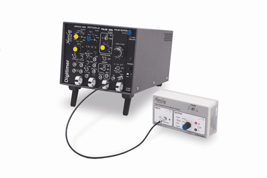
Ultimately, the output at (D) was fed into the NL510A PULSE BUFFER and NL800A STIMULUS ISOLATOR in order to convert the 2ms output pulses from the NL405 WIDTH/DELAY into a constant current stimulus of variable amplitude. However, it would be quite straightforward to remove the NL405 WIDTH/DELAY and take the NL301 PULSE GENERATOR output to trigger a different stimulator which might have internal pulse duration controls. Examples of these would include our DS2A, DS3 or DS7A.
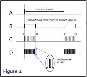
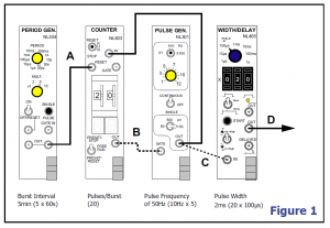
This simple arrangment of four modules is based around the NL304 PERIOD GENERATOR, the settings of which determine the interval between bursts. Once in the “ON” position, the module sends a regular output pulse at the interval set on the front panel. This output resets and activates the NL603 COUNTER, sending it’s output at (B) “high” until the count reaches the preset value of 20. But how is the counting done? The “high” output from the NL603 is used as a gate which allows the NL301 PULSE GENERATOR to pass a burst of pulses.
The burst of pulses are fed into the NL405 WIDTH/DELAY in order to give them width and also fed back to the input of the counter module. Once the counter detects 20 pulses, the output goes “low” thereby ending the gating pulse a t (B). This gating pulse remains “low” until the next reset pulse is sent by the period generator and a new burst is initiated.
Note: The dotted connections between modules indicate where rear connections are possible, while solid lines indicate links made by standard Lemo cables (NL951).