Application Note
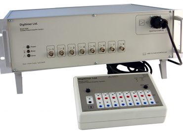
Using the DS5 Stimulator with the D188 Remote Electrode Selector
Introduction
The DS5 Biphasic Stimulator is commonly used with our D188 Remote Electrode Selector to present electrical stimuli to multiple sites at different times, however, in situations where the DS5 output is open circuit, voltage will build up and when the D188 is switched from all channels closed to one channel open, a transient voltage spike can appear at the output when the D188 channel is opened. This will occur even in the absence of any intended stimulation from the DS5. This phenomenon has been observed with the DS5/D188 combination, but could occur with our DS4 stimulator. It will not happen with any of our conventionally triggered pulse stimulators, such as the DS2A, DS3, DS7A/AH/R or DS8R.
The Cause
When the DS5 output is enabled and connected to a participant via a pair of stimulation electrodes, any voltage (including noise) applied to the DS5 analogue voltage input result in current flow. However, when the DS5 output is enabled and open-circuit or connected to a D188 with all channels switched off, the DS5 will generate an unpredictable and variable voltage as it attempts to pass current through the infinite resistance present at its output. This voltage will be significant and may have consequences when a D188 channel is activated.
As a D188 channel is turned on, the DS5 will detect the sudden change from an open-circuit output to the lower resistance of the stimulating electrode circuit. Because the DS5 is a constant current stimulator, this sudden drop in resistance causes the DS5 to lower the driving voltage at its output. However, this cannot happen instantaneously and as a result, some of the residual voltage present at the DS5 output passes through the newly activated D188 channel via the stimulating electrodes. This causes a transient voltage spike at the point when the D188 channel is activated, as illustrated in Figure 1.

Figure 1 An oscilloscope screenshot of a voltage spike coincident with the activation of a D188 channel at ~11ms (red oval). The intended stimulation pulse from the DS5 can be seen later, at ~27ms (orange oval). The blue trace is D188 Channel 1 voltage output measured across a resistor. The yellow trace is the input voltage applied to the D188 Channel 1 digital control pin.
The Solutions
Fortunately, there two relatively straightforward solutions to this potential problem. Because the issue arises as a result of the DS5 output being enabled and open-circuit during periods of no stimulation, the solutions require that the DS5 output is never allowed to become open-circuit.
The first solution would be to ensure that one of the D188 channels is always on and connected to the subject via stimulating electrodes even when stimulation is not occuring. The second requires the user to reserve one D188 channel as a dummy channel and fit it with a load resistor. This dummy channel should remain active whenever stimulation is not required. Keeping this channel active prevents the DS5 output from ever being in an open-circuit state and also ensures the subject is not electrically connected to the DS5 during periods of no stimulation.
If the second method is used, we recommend the operator fit a resistor across the outputs of the dummy D188 channel, which is comparable in resistance to the stimulating pathway (Figure 2). If the total electrode resistance is 5kohm, a 5kohm resistor should be used.

Figure 2 A schematic showing how a resistor placed on the output of a D188 channel can be used as a “dummy electrode channel” and remove the transient voltage spike seen during activation of another D188 channel.
Both methods ensure that the DS5 always has a resistance across its output, preventing it from developing a voltage when stimulation is not intended. As soon as one of the other D188 channels is activated, the dummy channel should be de-activated. The stimulus command from the DS5 control source can then be applied to via the analogue voltage input. This timing of this process is illustrated in Figure 3 and the results shown in Figure 4.

Figure 3 An illustration showing how a digital input to an unused “dummy channel” ensures that the DS5 output is never enabled and open-circuit during periods when stimulation is not intended.

Figure 4 Oscilloscope screenshot showing the absence of the initial voltage spike during D188 channel activation. In this case a resistor was placed across Channel 8 and this channel was kept active as a “dummy electrode channel” until the desired stimulation channel was turned on. The stimulation pulse from the DS5 can be seen at ~40ms. The blue trace is D188 Channel 1 output voltage measured through a resistor. The yellow trace is the input voltage to the D188 Channel 1 digital control pin.
Acknowledgements
Digitimer acknowledges the helpful assistance of Eva-Maria Dölker (Technische Universität Ilmenau, Department of Computer Science and Automation, Biomedical Engineering Group), who first described this phenomenon and provided the oscilloscope screenshots included in this application note.