Timing & Stimulation without a PC
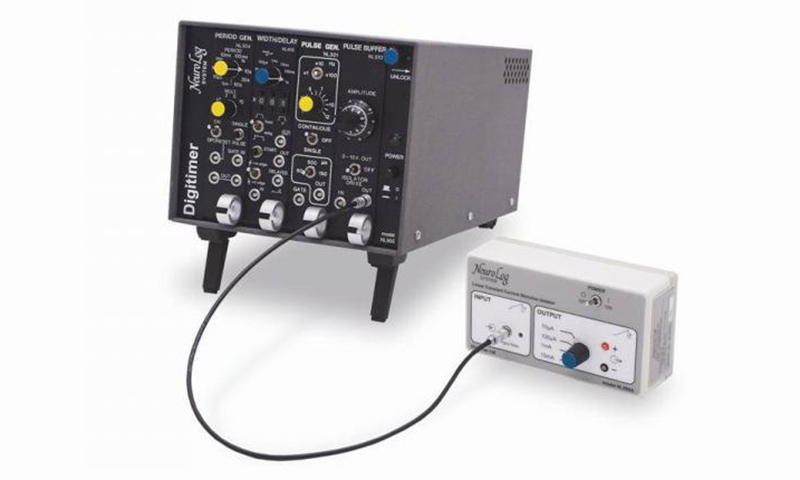
The NeuroLog System includes a range of modules which can be configured for multiple timing and stimulation protocols, without the need for a computer or software. While most modern data acquisition systems are capable of generating triggering/timing pulses for stimulation, they often require a certain amount of pre-configuration via software and any “on the fly” changes can be inconvenient to make during an experiment. With the NeuroLog System, a small number of timing modules can be employed to generate TTL compatible trigger pulses, used to control other devices, including the small, battery powered, constant current NL800A STIMULUS ISOLATOR. Because all settings are adjusted using familiar switches and dials, modifications to a protocol are easy to make, without the need to edit software protocols. The three schemes below illustrate how easy it is to set up a simple timing and stimulation protocol using just a few NeuroLog System modules.
EXAMPLE 1:
This arrangement provides single stimuli or continuous trains, with the pulse frequency continuously variable from 1s-1 to 1000s-1, three output pulse widths (50, 100, 150μs) and continuously variable output amplitude in four ranges from 0 to 10mA, with the stimulus output supplied by the NL800A isolator. Note that the NL510A can be used without the NL800A to generate a 0-10V non-isolated output for low voltage stimulation applications.
[su_lightbox type=”image” src=”/wp-content/uploads/2017/02/14510_Stimulation_Circuits_Example1-400×444-1-e1596032645403.jpg” mobile=”yes” class=””]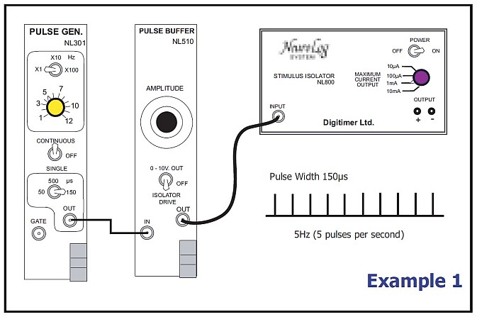
[/su_lightbox]
EXAMPLE 2:
By substituting the NL301 PULSE GENERATOR with the NL304 PERIOD GENERATOR, the pulse range can be greatly extended. Stimulus width can be adjusted by using the NL405 WIDTH/DELAY. Amplitude is controlled in the same manner as EXAMPLE 1.
[su_lightbox type=”image” src=”/wp-content/uploads/2017/02/14511_Stimulation_Circuits_Example2-673×383-1.jpg” mobile=”yes” class=””]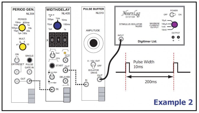 [/su_lightbox]
EXAMPLE 3:
The NL512 BIPHASIC BUFFER can be used in combination with two NL800A modules to allow a biphasic analogue signal to be converted into a constant current stimulus. The resulting configuration is “current out for voltage in”, meaning that the amplitude of the analogue input is proportional to the amplitude of the resulting constant current stimulus. Biphasic stimulation has the advantages that the preparation does not suffer the deleterious effects of “charging-up” and electrodes do not become oxidised. The biphasic analogue signal can be generated by a PC controlled DAC or by other NeuroLog System modules. If you want to stimulate several preparations using multiple sets of the NL512/NL800A configuration, the GATE input of the NL512 allows for digital output lines from a PC to enable each NL512 individually.
[su_lightbox type=”image” src=”/wp-content/uploads/2017/02/14509_Stimulation_Circuits_Example3-673×331-1.jpg” mobile=”yes” class=””]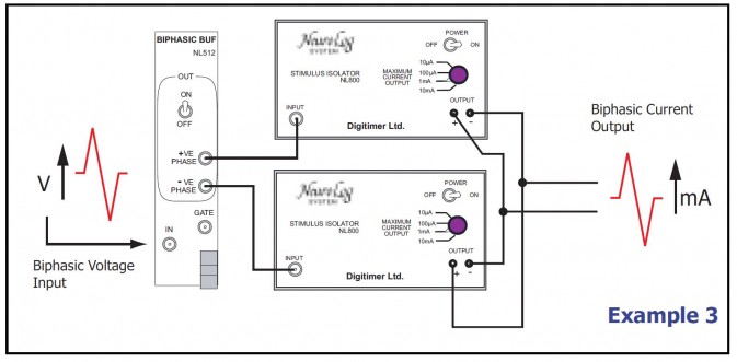 [/su_lightbox]
The complexity of these configurations can be greatly enhanced with additional modules. For instance, an NL603 Counter module can be used to define the number of pulses in a burst or even set the number of bursts. We look forward to introducing more complex, but highly flexible protocols in the coming months.