Description
DESCRIPTION
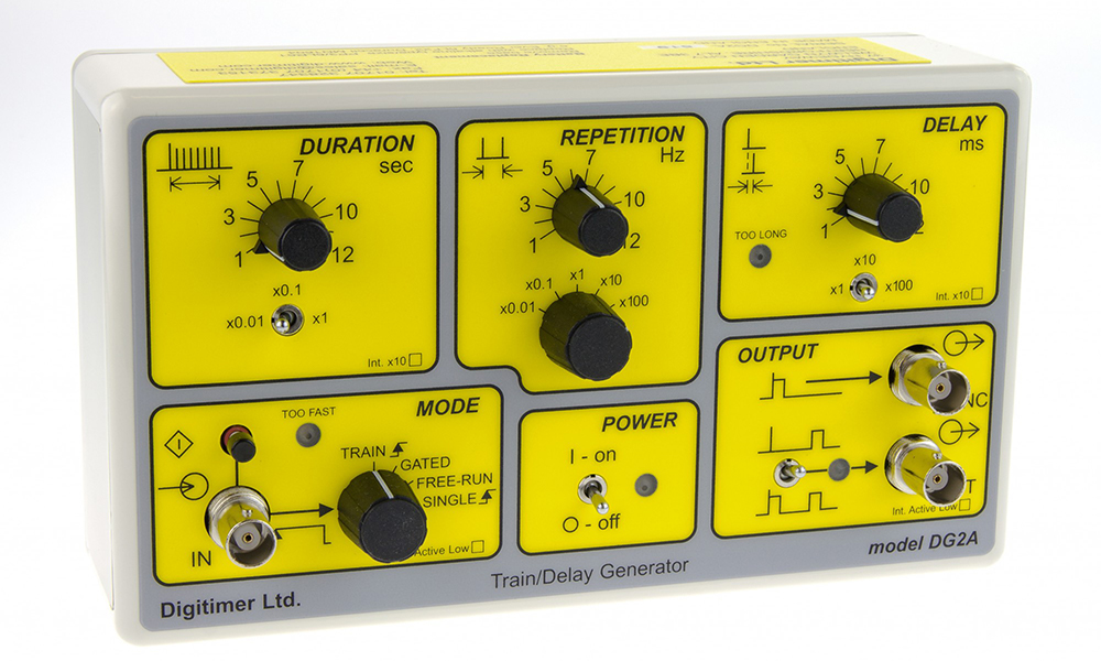
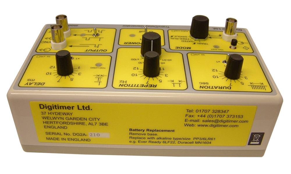
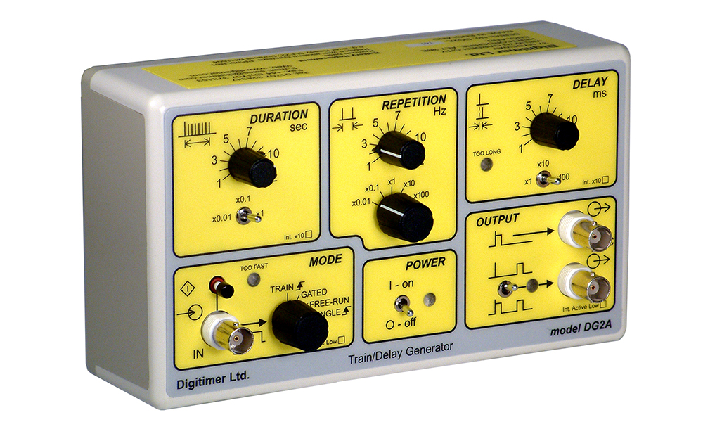
The DG2A Train Delay Generator small free-standing instrument has been designed for control of normal repetitive stimulation as well as for defining the Effective Refractory Period using a second, delayed pulse. The DG2A is especially useful as a frequency generator.
DS3 and DS7A isolated stimulators which have their own pulse duration controls can be used with our DS2A Train Generators and Delay Generators. The basic features of its predecessor the DG2 Trigger Generator are still included and have been extended to allow trains of pulses to be generated in response to input signals from other devices. The DG2A Train/Delay Generator has four operating modes which are detailed below:-
- Train – In TRAIN mode, a regular button press or TTL compatible trigger received at the IN socket of the DG2A is translated into a SYNC pulse train with a pulse repetition rate and train duration determined by the REPETITION and DURATION settings. The DELAY dial allows the introduction of a delayed pulse after each SYNC pulse which can be detected at the OUT-1/OUT-2 output.
- Gated – In GATED mode, the DG2A will output a train of pulses at the SYNC socket while the input at the IN socket is TTL high. This allows the operator to GATE the train of pulses on and off with an external device. The pulse repetition rate is determined by the REPETITION setting. The DURATION control has no function in this mode. The DELAY dial allows the introduction of a delayed pulse after each SYNC pulse, which can be detected at the OUT-1/OUT-2 output.
- Free-run – In FREE-RUN mode, the DG2A will continuously output SYNC pulses with a pulse repetition rate determined by the REPETITION setting while the unit is ON. The DURATION control has no function in this mode. The DELAY dial allows the introduction of a delayed pulse after each SYNC pulse which can be detected at the OUT-1/OUT-2 output.
- Single – In SINGLE mode, a single TTL compatible trigger received at the IN socket or push-button press is translated into a single SYNC pulse. The REPETITION and DURATION controls have no function in this mode. The DELAY dial allows the introduction of a delayed pulse after each SYNC pulse which can be detected at the OUT-1/OUT-2 output part of the DG2A.
The Digitimer team are on hand to discuss the full range of Train Generators and Delay Generators we have on offer. Contact by emailing [email protected] for more information.
GALLERY
DOWNLOADS
Product Information
DG2A Train/Delay Generator
DG2A Train/Delay Generator App 1
DG2A Train/Delay Generator App 2
References
Publications which cite use of the Digitimer DG2A can be found on Google Scholar.
ACCESSORIES
Supplied
- Operator’s Manual
- One PP3 battery (fitted)
Recommended
- D185-TC3 BNC Cable
- D185-TC3-2m BNC Cable
FAQS
The unit is powered by a standard 9V PP3 battery, which can be replaced by removing the four case screws, separating the case halves and inserting in the battery holder.
The DG2A is a trigger source and as such is not designed for direct connection to human subjects, however, when used in conjunction with one of our isolated electrical stimulators it is perfectly suitable and safe for use in human research in healthy volunteers or patients. For example when used to trigger our DS7A stimulator, the DS7A itself provides the necessary patient protection.
Inside the DG2A there is a bank of jumper switches, some of which are for factory use, but several others allow you to adjust certain output parameters including the train duration and delay settings. It is also possible to change the DG2A trigger input and pulse output from an active high TTL to active low TTL.
The controls of the DG2A do not allow for absolute precision and while the dial can be positioned to 20Hz, the only way to verify the frequency would be to monitor the output on an oscilloscope or within data acquisition software. That said, if the dial is set to 20Hz, the actual output should be within 5% of the expected value.
Yes, the DG2A Power On LED flashes intermittently when the DG2A is switched on – this is not an indication that it is delivering an output, but having a flashing LED does reduce the battery use when the DG2A is switched on. Actual pulse output is shown by the amber LED in the output zone of the front panel.
A single DG2A cannot accomplish this, however, if you link two together you can set one to “free-run”, delivering a pulse indicating the start of each train and the second DG2A can be set to receive this pulse and output a burst of pulses in “train” mode. There is an application note that shows how this is done.


