Application Note
Measuring Physiological Pressures with the NeuroLog System
Overview
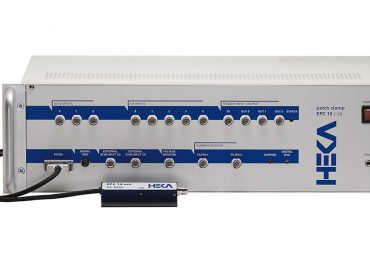
The NeuroLog System is more than just an electrophysiology tool, as the range of modules also includes the NL108A Pressure Amplifier which allows you to record physiological pressures independently or alongside your electrophysiological data. Because measurement of a single pressure parameter requires only one module to be installed into the NL900D or NL905 Case & Power Supply Unit, a single rack can be used to amplify pressure readings from up to 13 preparations simultaneously.
The NL108A provides two gain settings, one appropriate for blood pressure (1V output for 100mm Hg) and the other for low pressure measurements such as intra-tracheal pressure (100mV output for 1cm of water). The amplifier has a built in calibration feature for these two ranges, as well as a push button zero function as well as a sensitive zero offset dial.
What pressure transducers can I use?
Although the NL108A is designed to mate perfectly with our own NeuroLog System pressure transducers (NL108T2 or NL108T4), due to its internally adjustable gain and bridge excitation voltage, it can be used with a variety of other standard pressure transducers.
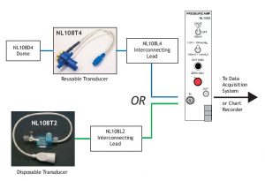 Digitimer supply two types of transducer, the NL108T2 which is a disposable type and the NL108T4 which is reusable. The NL108T4 needs to be fitted with disposable domes (NL108D4T) before use. Although the NL108T2 is described as single-use, many of our customers find that for non-human research use, the transducer can be used several times before it need to be replaced.
In order to connect either transducer to the input of the NL108A an appropriate interconnecting lead is required. Digitimer recommend use of our NL951B-1m or 2m Lemo to BNC cables to take the amplified signal from the Pressure Amplifier into an acquisition interface with BNC input sockets. Please note that although the NL108A has been designed especially for our own range of pressure transducers, due to its internally adjustable excitation voltage and gain settings, it can be set up to use with many other standard pressure transducers and even strain gauges.
Setup & Calibration with third party transducers
The NL108A is supplied calibrated for any of our supplied NeuroLog pressure transducers which have a stated accuracy. If a more precise calibration is required, or a different transducer is to be used, you will need to perform the following procedure.
1) Check the data sheet of the particular transducer you wish to use with the NL108A for its EXCITATION VOLTAGE at its rated output (in the case of the NeuroLog transducers this is 10.0V). The NL108A is designed so that the excitation voltage may be varied between 0 and 11 volts with the preset mounted on the board. This is so that damaging voltages cannot be applied to the NeuroLog transducers. If voltages up to 24 volts are required a single resistor change is required (see circuit diagram and assembly drawings for the NL108A).
2) Attach a good isolated voltmeter between the two pins on the NL108A printed circuit board marked BRIDGE VOLTAGE + and -. The voltages at these pins are symmetrical above and below 0V (i.e. ground or earth). DO NOT GROUND EITHER OF THESE TWO PINS. In general, an oscilloscope is not accurate enough to use in setting the excitation voltage – use a good voltmeter.
3) Plug the NL108A module into the rack with the power OFF, leaving several empty bays to the left of the module so that the trimpot marked set bridge voltage can be adjusted. DO NOT CONNECT THE PRESSURE TRANSDUCER YET.
4) Switch on the NL905 or NL900 rack and adjust the set bridge voltage trimmer to give the correct excitation voltage at the bridge voltage pins.
5) The pressure transducer can now be plugged into the NL108A module and the voltmeter disconnected after ensuring no drop in voltage.
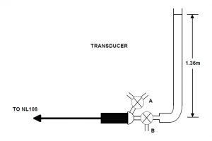 6) Attach a three-way stop-cock to each of the two points of the transducer as shown in the diagram. One of these stop-cocks (A) is closed. The second, at port B, is set up so that it can either vent the port to the atmosphere (i.e. zero pressure), or set to connect the port to a piece of 3 or 4mm inside diameter plastic tubing. The tubing is suspended vertically and filled with water to a height of 1.36 meters (the pressure exerted by a 1.36m column of water is equal to that for a 100mm column of mercury).
7) With the port B stop-cock set to atmosphere, adjust the NL108A ZERO ADJ front panel potentiometer so the 0V is recorded at the OUT sockets. (CALIB switch in OFF position and the pressure range toggle switch in the 1.0V = 100mm position). Now switch the port B stop-cock so that the column of water is connected to the transducer. The output of the NL108A should give an output of +1.0V, if the excitation voltage and sensitivity of the transducer are correct. If not, check the BRIDGE VOLTAGE setting again (also double check the transducer data sheet).
8) Deviations from 1.0V output (for the 1.36m pressure) can be adjusted with the trimmer on the NL108A printed circuit board labelled GAIN. Small adjustments can also be made with the BRIDGE VOLTAGE setting – but be careful not to exceed the limits for your particular transducer.
9) When correctly set up, pushing the OUT GND push-button should produce the same effect on the output as opening port B to the atmosphere. Switching the CALIB toggle switch to its 1.0V position should also produce the same output deflection as opening port B to the 1.36m column of water.
10) Steps 6 and 9 can be repeated for the 100mV = 1cmH2O switch position. In this case, however, the column of water should be 10cm for 1.0V output deflection.
Using the “Out Ground” and Calibration Switches
The OUT GND push-button is used to locate the zero pressure dc level on the output recording. A 0.0V to 1.0V calibration deflection is produced on a recording trace by switching the CALIB switch to 1.0V and pushing the OUT GND push-button a couple of times. Similarly for the 0.0V to 100mV calibration deflection.
Recent References
Below is a selection of recent papers that have used the NeuroLog System NL108A to make physiological pressure measurements.
Guo, J., Li, R., Wang, J. et al. Blood Pressure Change in Intrafascicular Vagal Activities. J. Shanghai Jiaotong Univ. (Sci.) 26, 47–54 (2021). https://doi.org/10.1007/s12204-021-2259-7
Burns, P., C. L. Herry, K. J. Jean, Y. Frank, C. Wakefield, M. Cao, A. Desrochers et al. “The neonatal sepsis is diminished by cervical vagus nerve stimulation and tracked non-invasively by ECG: a preliminary report in the piglet model.” arXiv preprint arXiv:2002.04136 (2020).
Lifang Huo, Yiting Gao, Dongfang Zhang, Shengnan Wang, Yu Han, Hongchao Men, Zuxiao Yang, Xia Qin, Ri Wang, Dezhi Kong, Hui Bai, Hailin Zhang, Wei Zhang, Zhanfeng Jia, Piezo2 channel in nodose ganglia neurons is essential in controlling hypertension in a pathway regulated directly by Nedd4-2, Pharmacological Research, Volume 164, 2021, 105391, ISSN 1043-6618, https://doi.org/10.1016/j.phrs.2020.105391.
Smith, T. M., Lee, D., Bradley, K., & McMahon, S. B. (2020). Methodology for quantifying excitability of identified projection neurons in the dorsal horn of the spinal cord, specifically to study spinal cord stimulation paradigms. Journal of Neuroscience Methods, 330, 108479. https://doi.org/https://doi.org/10.1016/j.jneumeth.2019.108479
Castel, A., Burns, P. M., Benito, J., Liu, H. L., Kuthiala, S., Durosier, L. D., … Frasch, M. G. (2021). Recording and manipulation of vagus nerve electrical activity in chronically instrumented unanesthetized near term fetal sheep. Journal of Neuroscience Methods, 360, 109257. https://doi.org/https://doi.org/10.1016/j.jneumeth.2021.109257
If you would like to learn more about using the NeuroLog System to make pressure measurements, then please contact us.