DS3 Output Clamp
The Why, When and How
Capacitance build up is often associated with repetitive in vitro stimulation
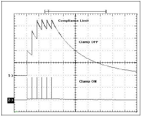
When a high output impedance constant current stimulator is used to deliver a stimulus to a cell or tissue in vitro, the cell will retain some of that energy between stimuli and “charge-up”. If this cell is repetitively stimulated at high frequency, this charge will not dissipate between stimuli and build up. As the capacitance increases, the stimulator will eventually reach its voltage compliance limit, as illustrated in the upper trace of the figure below.
How can I avoid this problem?
Fortunately, for users of our DS3 isolated constant current stimulator, our engineers came up with a clever solution. The DS3 incorporates a user enabled “CLAMP circuit” that operates for 20 μs after each stimulus pulse. When activated, this circuit will discharge cells with capacitances as high as 1000 pF, as indicated in the following oscilloscope screenshot. So, while other stimulators may struggle to deliver consistent stimuli under these conditions, the DS3 can be relied on to output reproducible pulses again and again.

Stimulus – A burst of 6 x 220 μA, 200 μs pulses with an ISI of 10 ms.
Scales – 25 ms/div., 20 V/div.
Dummy Cell – 1100 pF in parallel with ~50 MW.
Trace 1 – CLAMP OUT: Shows the effect of no clamp on the output. NOTE that the 3rd stimulus is NOT the same amplitude as the previous two as the cell is charged and the stimulator has reached its 90 V limit.
Trace 2 – CLAMP IN: Here the Output Clamp is automatically activated after each stimulus. NOTE that all six stimuli are presented to the preparation at equal amplitude.
How do know if the clamp is activated in my DS3?
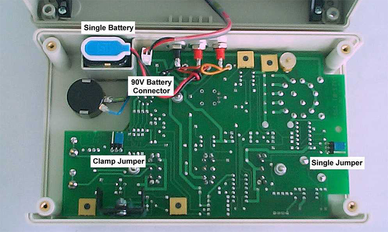
By default the output clamp is inactive when the DS3 is despatched, so it is important that you decide if it is a feature you will require. Activating the output clamp is very straightforward and is detailed in the operator’s manual. Briefly, the four screws which hold the DS3 case together need to be removed and the two case halves carefully separated. The Clamp Jumper is clearly identified on the printed circuit board (illustrated below), which is labelled to show the correct jumper position for IN (active) and OUT (inactive).


