Broken Stimulator or just Flat Batteries?
 Keep Checking your batteries!
In order to ensure our stimulators are suitable for demanding electrophysiological applications, Digitimer often makes use of batteries to provide a low noise, but high voltage power source. Anyone familiar with our DS2A and DS3 stimulus isolators should already know that at some point, batteries will start to fail and stimuli will become unreliable or weak.
As a result, we recommend that you not only carry out regular checks of the batteries in order to learn how often they are likely to need replacing, but also make sure all potential users understand how to check and replace batteries should they need to. You might be surprised to learn how many stimulators our service department has received for repair, only to discover they just needed a new set of batteries.
Instructions for battery checking and replacement are found in our operator’s manuals, however, we would like to take this opportunity to describe the process, with specific reference to our popular DS2A and DS3 stimulators.
How can I tell if the batteries are failing?
The DS2A and DS3 have one 9V PP3 control battery which is used to power the stimulator control circuitry and ten more PP3 batteries located in the battery compartment, which provide the compliance voltage source for the stimulator. Failure of either the control or compliance batteries will result in a weakening of the output, which will be demonstrated by a smaller or absent stimulus artefact and response. You certainly don’t want to want to find out the batteries are failing half way through a crucial experiment, so it makes sense to give them a regular health check.

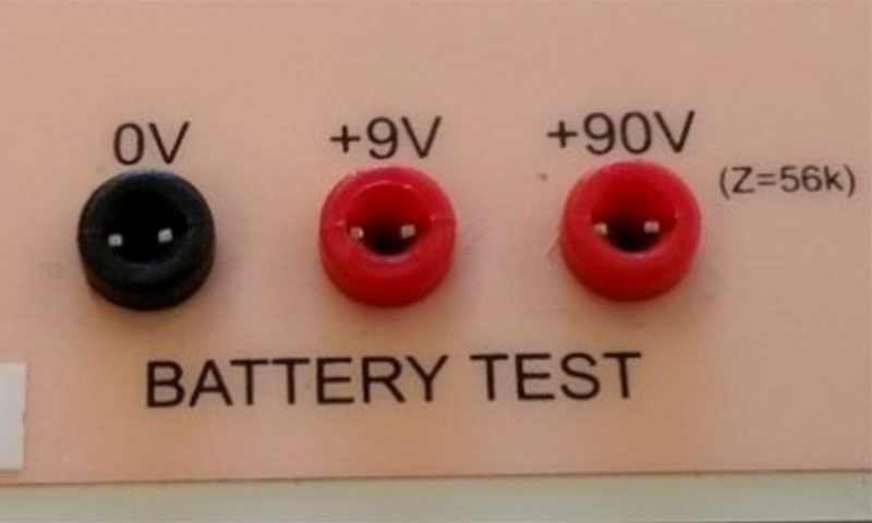
Users of our DS2A, DS3 or DS4 stimulators will have noticed the battery test sockets on one side of the case. These sockets give you access to the battery voltages within the stimulator, allowing you to check status of all batteries without having to open up the device. Voltages are most easily measured using the probes of a digital multi-meter set to measure a DC voltage in the expected range. However, it is important to ensure that the voltages are checked while the internal batteries are being stressed and the best way to do this, is to set the stimulator to deliver a long (2s) output pulse, trigger the delivery of a stimulus via your usual stimulation electrodes immersed in saline or aCSF and measure the test socket voltages using the multi-meter. Quite often, the stimulator battery pack will show a normal voltages when the batteries are at rest, but as soon as a stimulus is being delivered, the voltage drops significantly, indicating failing batteries.
How low is too low?
If the control battery voltage is below 6.5V, then the control circuit within the stimulator will start to fail soon and battery replacement is recommended. The appropriate time to replace the compliance batteries is determined by the voltage that is required to pass the required stimulus. In the case of our constant voltage DS2A, if the battery voltage has declined to the extent that it is below the voltage setting normally used, then the batteries clearly need replacing. For constant current devices like the DS3 or DS4, it is important that the battery voltage is adequate to pass the requested current through the stimulation electrode(s). For example, if you typically stimulate with 10mA through a 5kohm stimulating electrode, Ohm’s law predicts that the voltage required to do this would be 50V, therefore it is important to ensure that the battery voltage never falls to this level. If you don’t know the typical impedance of your stimulation pathway, then you can use a multi-meter to measure it, giving you some idea of the lowest voltage you can allow the stimulator battery pack to drop to.
Replacing the batteries
In the case of the DS2A and DS3, it is necessary to remove all four of the case screws and slide the two halves of the stimulators apart, taking care not to strain the interconnecting cable between the stimulator motherboard and the battery pack.


Once separated, the two halves can be completely disconnected from each other by unclipping the small white plug next to the control battery housing.
At this point the control battery can be removed and replaced.

Access to the remaining 10 batteries is achieved with the removal of the four screws holding the black battery pack in place. Once these are removed, the battery pack can be lifted away and inverted, revealing the ten individual batteries and associated wiring harness.

Each battery should be removed from its battery clips and replaced with a new good quality alkaline equivalents. Note that we do not recommend use of rechargeable batteries as their voltages can decline significantly without any warning, making them less reliable than disposable batteries.
The stimulator can then be reassembled, taking care to re-attach the battery pack cable and ensuring it is not pinched by the case halves when they are brought back together.
Of course, if you find that your stimulator still doesn’t work after a new set of batteries have been installed, then please contact Digitimer or our local representative and we can discuss arranging for the stimulator to be repaired.