Description
DESCRIPTION
The D175 Electrode Impedance Meter from Digitimer is a compact battery powered device designed to allow checking of electrode impedances prior to recording or stimulating through surface electrodes attached to the skin.
In the case of electrical stimulation, high electrode impedances can reduce the amount of current that can pass through the target tissue, resulting in lower than expected stimulation and a poor evoked response. Likewise, high impedances will reduce the signal to noise ratio and therefore the quality of recordings, such as ECG, EEG and EMG that rely on low impedance surface electrodes.
The D175 Electrode Impedance Meter, is a tool that allows suitably trained operators to rapidly assess surface electrode impedances in order to decide if they are low enough for the procedure being undertaken. It features green/red bi-colour LEDs allowing the operator to set a threshold impedance at which an LED will light as red rather than green. This facilitates electrode impedance checking, by providing the operator with an easily visible indication of “good” (green) or “bad” (red) electrode impedances. The impedance values that the D175 can display are 0, 0.5, 2, 3, 5, 7, 12, 20, 30, 50 kohm.
The D175 measures the total impedance through a pair of electrodes placed on the skin, by passing a very small biphasic (charge neutral) current between them. Once electrodes have been positioned on the recording/stimulation sites, a pair of electrode lead wires should be connected to the RED and BLACK electrode sockets (1.5mm DIN 42802) on the top of the D175. The sockets are colour coded for no reason other than to help the user identify which electrode is being used as the reference. With the electrodes connected and with the D175 switched ON (and in METER MODE), the D175 should display the measured impedance.
Having identified one or more electrodes that have a “good” impedance level, these can then be used as reference electrodes for the remainder. If bad/high impedances are found, it may be necessary to replace one or both of the electrodes following additional skin preparation, according to the standard recommended practice.
For display purposes, measured impedances are rounded up to the next highest displayable value, i.e 4 kohm lights up the 5 kohm LED. By pressing and holding the Power Button for longer than 4 seconds, the D175 will enter the SETUP MODE and allow the operator to change the level at which the LEDs illuminate green or red. In SETUP MODE, the LED corresponding to the highest “good” (green) level will flash green. The D175 preserves battery power by switching off if a button is not pressed for a period of greater than one minute.
SPECIFICATIONS
Electrode Connection Sockets
Red and Black 1.5mm DIN42802 Sockets
Current Frequency
30 Hz ± 10% (biphasic square wave)
Compliance Voltage
300mV
Maximum Current
±6.8µA
Indicators
Bi-colour LED array for impedance display and battery test
Power Button
Brief Press powers unit ON/OFF (unit switches OFF automatically after being on for 1 minute to preserve batteries). Press & hold for longer than 4s to initiate SETUP MODE
Battery Test Button
Brief Press powers unit ON, press again & hold to test batteries
Battery Type
2x 1.5V AA (LR6, FR6, ZR6)
Dimensions
110mm x 66mm x 25mm
Weight
152g (including batteries)


DOWNLOAD BROCHURE

PUBLICATIONS
Moser, H., Leitner, M., Eichelberger, P., Kuhn, A., Baeyens, J. P., & Radlinger, L. (2019). Pelvic floor muscle displacement during jumps in continent and incontinent women: An exploratory study. Neurourology and Urodynamics, 38(8), 2374–2382. https://doi.org/10.1002/nau.24161
Seidl, L., Tosovic, D., & Brown, J. M. (2017). Test-retest reliability and reproducibility of laser-versus contact-displacement sensors in mechanomyography: Implications for musculoskeletal research. Journal of Applied Biomechanics, 33(2), 130–136. https://doi.org/10.1123/jab.2016-0085
Tosovic, D., Seidl, L., Ghebremedhin, E., & Brown, M. J. (2015). Determining minimal stimulus intensity for mechanomyographic analysis. Journal of Electromyography and Kinesiology, 25(5), 749–753. https://doi.org/10.1016/j.jelekin.2015.06.003
Busch, A., Blasimann, A., Henle, P., & Baur, H. (2019). Neuromuscular activity during stair descent in ACL reconstructed patients: A pilot study. Knee, 26(2), 310–316. https://doi.org/10.1016/j.knee.2018.12.011
Saeuberli, P. W., Schraknepper, A., Eichelberger, P., Luginbuehl, H., & Radlinger, L. (2018). Reflex activity of pelvic floor muscles during drop landings and mini-trampolining-exploratory study. International Urogynecology Journal, 29(12), 1833–1840. https://doi.org/10.1007/s00192-018-3664-9
Leitner, M., Moser, H., Eichelberger, P., Kuhn, A., & Radlinger, L. (2019). Pelvic floor muscle activity during fast voluntary contractions in continent and incontinent women. Neurourology and Urodynamics, 38(2), 625–631. https://doi.org/10.1002/nau.23911
Koenig, I., Eichelberger, P., Leitner, M., Moser, H., Kuhn, A., Taeymans, J., & Radlinger, L. (2020). Pelvic floor muscle activity patterns in women with and without stress urinary incontinence while running. Annals of Physical and Rehabilitation Medicine. https://doi.org/10.1016/j.rehab.2019.09.013
Busch, A., Henle, P., Boesch, L., Blasimann, A., & Baur, H. (2019). Neuromuscular control in patients with acute ACL injury during stair ascent – A pilot study. Sports Orthopaedics and Traumatology, 35(2), 158–165. https://doi.org/10.1016/j.orthtr.2019.04.002
Swafford, A. P., Kwon, D. P., MacLennan, R. J., Fukuda, D. H., Stout, J. R., & Stock, M. S. (2019). No acute effects of placebo or open-label placebo treatments on strength, voluntary activation, and neuromuscular fatigue. European Journal of Applied Physiology, 119(10), 2327–2338. https://doi.org/10.1007/s00421-019-04219-1
Faes, Y., Banz, N., Buscher, N., Blasimann, A., Radlinger, L., Eichelberger, P., & Elfering, A. (2018). Acute effects of partial-body vibration in sitting position. World Journal of Orthopaedics. ncbi.nlm.nih.gov. https://doi.org/10.5312/wjo.v9.i9.156
Ballmer, C., Eichelberger, P., Leitner, M., Moser, H., Luginbuehl, H., Kuhn, A., & Radlinger, L. (2020). Electromyography of pelvic floor muscles with true differential versus faux differential electrode configuration. International Urogynecology Journal, 31(10), 2051–2059. https://doi.org/10.1007/s00192-020-04225-4
Koenig, I., Eichelberger, P., Luginbuehl, H., Kuhn, A., Lehmann, C., Taeymans, J., & Radlinger, L. (2020). Activation patterns of pelvic floor muscles in women with incontinence while running: a randomized controlled trial. International Urogynecology Journal. https://doi.org/10.1007/s00192-020-04334-0
FAQS
The D175 measures the total impedance through a pair of electrodes placed on the skin, by passing a very small biphasic (charge neutral) current between them. Once electrodes have been positioned on the recording/stimulation sites, a pair of electrode lead wires should be connected to the RED and BLACK electrode sockets (1.5mm DIN 42802) on the top of the D175. The sockets are colour coded for no reason other than to help the user identify which electrode is being used as the reference. With the electrodes connected and with the D175 switched ON (and in METER MODE), the D175 should display the measured impedance. If the 7kΩ LED is lit, the actual total impedance lies somewhere between 5 and 7 kΩ.
Having identified one or more electrodes that have a “good” impedance level, these can then be used as reference electrodes for the remainder. If bad/high impedances are found, it may be necessary to replace one or both of the electrodes following additional skin preparation, according to the standard recommended practice.”
When stimulating, a lower electrode impedance reduces the voltage that a constant current stimulator needs to use to pass the requested current. A low impedance also allows the maximum current to be higher before the stimulator goes “out of compliance”. For recording electrodes, lower impedances can drastically improve the signal to noise ratio of the recordings and good skin preparation and cleaning is always recommended in order to obtain the best quality recordings.
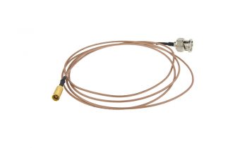
The two electrode sockets on the D175 are a male 1.5mm DIN42802 connector which is a type commonly used on medical electrodes which for safety reasons need to have touch-proof connectors.