Description
DESCRIPTION
Introduction
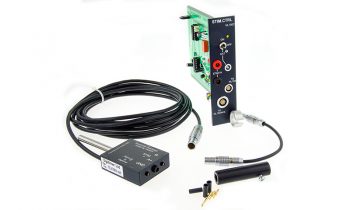
The NL102G DC Pre Amplifier is designed specifically for biological recording. With features such as capacity neutralization, current injection, low leakage current and low DC drift, it is particularly suitable for intracellular measurements through high resistance fluid-filled electrodes. The input stage, is conveniently located at the end of a 2m cable for direct attachment to a micromanipulator. Other features include electrode impedance check, calibrator, stimulus bridge balance and DC level adjustment. The NL102G DC Pre Amplifier is supplied with the NL412 Pulse box, which acts as a “buzz” control to facilitate electrode impalement.
Compact Remote Headstage
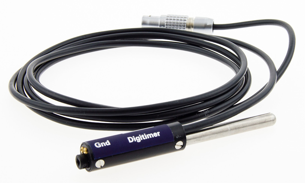
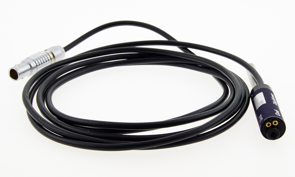
The first stage of the NL102G DC Pre Amplifier is fitted in a metal tube at the end of a 2m cable. This unit is calibrated against the module supplied with it; it is NOT interchangeable with other NL102G modules without re-calibration (the serial numbers on both the headstage and module should match). The central 2mm input socket (+In) is the capacity-compensated signal input through which current can be injected. The shield socket (Shd) is the ‘x1’ output and may be used as a capacitance ground or shield at the preparation. If not required for this purpose it must be left unconnected. NB: this is a major difference between the NL102 and the NL102G DC Pre-Amplifiers. The final socket is the system ground (Gnd) and connection should be made to the preparation via the indifferent electrode. DO NOT ATTEMPT TO USE OVERSIZE PLUGS WITH THE HEADSTAGE SOCKETS, as pins greater then 1.0mm/2.0mm will damage the sockets.
Electrode Connections
Fluid-Filled Pipette Electrodes Pipettes can only be attached to the headstage by using a compatible electrode chamber. Metal electrodes can be connected using a NL04 electrode holder alternatively the user must adapt a 2mm pin connector (supplied) to suit the particular electrodes used. A common solution to this problem is a short length (i.e. 5-10mm) of hypodermic needle tubing soldered to the 2mm pin (keep this connection as short as possible for low interference). Because metal microelectrodes exhibit large polarization potentials (up to 500mV) and behave like capacitors in parallel with a very large resistance (ie 200-500Mohms), they are not often used for DC measurements. When the NL102G is used for low noise, AC coupled measurements (e.g. extracellular recordings through tungsten microelectrodes) it is advisable to connect a large value resistor (ie 50Mohms) between the (+In) input and the ground. This resistor does not degrade the recording characteristics of such electrodes but eliminates the large, unstable junction potentials which may saturate the NL102G DC Pre Amplifier input. The User must supply a suitable indifferent electrode – the nature of this electrode will depend on the sort of recording electrodes used.
DC Level
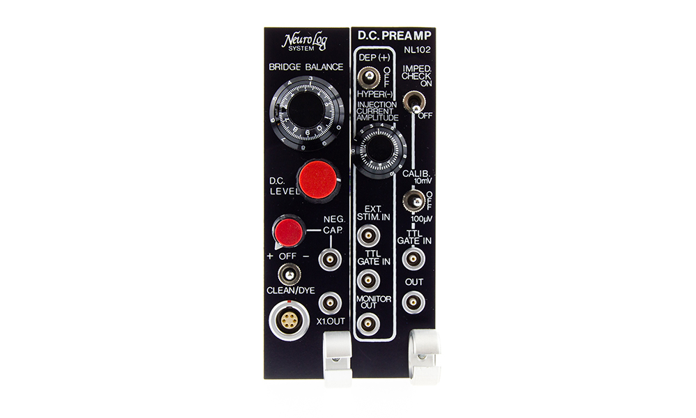
The DC level adjustment control on the left-hand panel provides a means of backing off DC voltage present at the electrodes. It operates between the x1 output of the DC pre-amplifier and x10 amplifier. The x1 output is therefore always a true measure of the DC potential existing at the electrode system, whereas the x10 output can be set to give zero over a range of standing electrode potentials. The range of this control will enable the x10 output to be set to zero over a range of ±2V at the electrode input to the system.
Monitor Out
This socket provides a voltage proportional to the current injected into the electrode system by the current injection circuitry fitted to the NL102G. The calibration of this system is such that a maximum signal of ±10 volts at the socket represents full scale injection current for the range selected by the jumper plug on the left-hand module board. The ranges provided by this selector are 10nA, 20nA, 50nA and 100nA but it should be noted that the MONITOR output signal will only truly measure the injection current if the electrode impedance does not exceed values of 1000Mohms, 500Mohms, 200Mohms and 100Mohms respectively.
Out
This output connection is the x10 DC Current amplifier output. As the output dynamic range is ±11V, the output saturates at an input signal of ±1.1V. In addition to this ±1.1V, up to ±2V, with respect to the input, can be offset with the DC LEVEL control before the output saturates.
Impedance Check
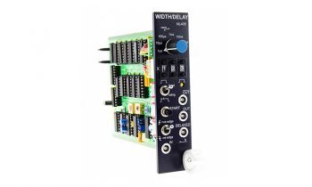
When the IMPED CHECK switch is put in the ON position, a 1nA current is injected through the (+In) input. Without a TTL input at the TTL GATE IN input, the impedance check waveform is an asymmetric positive rectangular wave, (approximately 150Hz) with an amplitude of 1mV per Mohm at the x1OUT socket. (Note that the MONITOR OUT signal does not reflect the electrode resistance). A TTL pulse (eg from an NL403 DELAY WIDTH module) applied to the CALIB TTL GATE IN socket (located immediately beneath the CALIB switch) results in a 1nA impedance check current, with the TTL pulse timing, injected when the IMPED CHECK switch is in the ON position. (The TTL pulse signal can be adjusted so that it occurs at the end of each oscilloscope sweep during penetration, for example). TTL pulses longer than the 150Hz period will merely gate the 150Hz waveform on. The waveform recorded during the injection of the IMPED CHECK current depends on the nature of the recording electrode and on the setting of the NEUTRALIZATION control. Pipettes have a flat-topped waveform, but metal electrodes have a complicated waveform reflecting a small series resistance and a parallel resistance and capacitance.
Bridge Balance
Electrode impedance (for pipettes) can be determined by another method in addition to the IMPED CHECK. When the CURRENT INJECTION switch is put in either the DEP or HYPER position, the AMPLITUDE dial is adjusted to give a few nA and the BRIDGE BAL dial is adjusted to restore the baseline to where the BRIDGE BAL control is correctly adjusted – it will now indicate the resistance of the pipette at the + input, with a dial reading of 10.0 corresponding to 100Mohms if 100nA is selected, for the 50nA range this is 200Mohms, or 500Mohms for 20nA, or 1000Mohms for 10nA. Whenever current is injected through the microelectrode at the (+In) input (except for the IMPED CHECK current, of course), the BRIDGE BAL control may be adjusted to cancel out the resulting voltage across the microelectrode, giving the effect that the baseline is stationary during current injection. Note that the BRIDGE BAL reading reflects the total (ie electrode plus membrane) resistance during intracellular amplifier recordings. Also, that the BRIDGE BAL feature operates on the x10 out only, the x1 output at all times shows the sum of the electrode potential and the potential developed across the electrode impedance by the injected current.
Calibrator
100μV or 10mV calibration signals, selected by the CALIB toggle switch are available for use with the x10 amplifier section. The timing of the calibration signal is the same as that for the IMPED CHECK (i.e. a 150Hz rectangular wave or a pulse determined by the same CALIB TTL GATE IN signal). The CALIB signal is however negative, rather than positive as for the IMPED CHECK. Thus, these two cannot be used simultaneously; they will add algebraically. The TTL gate facility for the calibration signal is especially useful in situations such as averaging synaptic potentials when a calibration signal positioned on each trace will result in a calibration of the overall resulting average.
Current Injection
The set of controls and connectors enclosed by the white lines on the right-hand front panel are all concerned with current injection. The toggle switch, 10-turn potentiometer and TTL GATE IN socket determine one current source; the EXT STIM IN socket determines the timing and amplitude of a second source which is added algebraically to the first. With no input at the TTL GATE IN socket, a current with its amplitude determined by the 10-turn dial flows when the toggle switch is activated (up for depolarizing (+) and down for hyperpolarizing (-) current flow). With a TTL input, the current set on the dial and switch flows when the TTL input is high. A signal applied to the EXT STIM IN socket causes a current to flow independently of the toggle switch. ±10.0V at this input corresponds to ±100nA*. Note that the total amount of current that can be passed even with both sources activated is ±100nA*. The MONITOR OUT shows the total current injected. * Depending on jumper selection this can be 100nA, 50nA, 20nA or 10nA
Neutralization
The capacity at the + input of the headstage can be neutralized by setting the NEUTRALIZATION control. Either the IMPED CHECK or CURRENT INJECTION can be used for this adjustment. Optimal adjustment produces the fastest risetimes on these signals without overshoot or ringing. Excessive clockwise adjustment of the NEUTRALIZATION control will result in oscillation and current injection. Over compensation also increases noise levels, so careful adjustment of this control is essential for optimum performance. During penetration and until the precise waveforms in recordings are importance, it is advisable to use the NL102G in a slightly undercompensated state. With low impedance electrodes, and metal microelectrodes, the NEUTRALIZATION control is usually set in the minimum (ie fully anti-clockwise) position.
NL412 Pulse Box
It has been found that electrode penetration of the cell membrane is improved if the headstage DC Current amplifier is in an oscillating condition. Newer NL102G’s are fitted with an input (NEG CAP) which connects to the NL412 Pulse Box (included with new NL102G’s). The NL412 has a push button which when depressed, activates the capacity compensation circuit applying maximum compensation. This normally induces oscillation in the current injection system and aid impalement of the cell. Note that the older NL102G DC Pre Amplifier had a button on the front panel rather than a socket for the NL412 to connect to.
Clean/Dye Control
This is a switch which, when operated, causes high injection currents to be applied to the electrode. It can, therefore, be used to dye stain the preparation at the end of an experiment. If operated in an alternate +/- condition it will also facilitate clearing of a blocked fluid-filled electrode should this become necessary during the experiment.
GALLERY
DOWNLOADS
Product Information
NL102G DC Pre-Amplifier Manual
Intracellular (DC) Recording Application Note
References
Publications which cite use of the Digitimer Neurolog System can be found on Google Scholar.
SPECIFICATIONS
Input resistance : 1011ohms
Voltage gain : x1, x10 fixed
Input Voltage Range (to output saturation) : ±1.1V
Absolute maximum input voltage range : ±12V
Gate leakage current : adjustable to zero
Input capacity neutralization range : 0 to 30pF
Risetime (zero source resistance) : 1μsec
(20Mohms source resistance) : 15μsec
Polarization current range* : 0 to ±100nA/50nA/20nA/10nA
Maximum noise level (10kHz bandwidth, referred to input)
(zero source resistance) : 5μV pk-pk (1μV RMS)
(10Mohms source resistance) : 180μV pk-pk (36μV RMS)
Zero stability (referred to input) : ±100μV/day
DC level offset range (referred to input) : ±2V
Output impedance : 600ohms
Output voltage range : ±11.0V
Electrode impedance check (150Hz square wave) : 1mV/Mohms (at +In)
Bridge balance range* : 0 to 100Mohms, 0 to 200Mohms, 0 to 500Mohms, 0 to 1000Mohms
Calibrator : 10mV/100μV 150Hz square wave
External stimulus input range* : ±10V corresponds to ±100nA/50nA/20nA/10nA
* Depending on internal jumper setting
